MVisionPro Engineering Library · guide
Deciding whether the depth of field covers your part-position spread
In short
Put the reference plane in the middle of the spread of part positions, then compare that spread, plus the reserve you accept, with the interval the calculator returns. Set the minimum f-number that covers both: a larger f-number is a smaller opening, so it widens the interval but costs light and enlarges the diffraction spot. "Sharp enough" is not in that formula: for a code it is the decoder's required read result across the depth range, and for a measurement it is calibrated error and repeatability inside the allocated budget. The f-number the arithmetic gives you is a candidate, accepted only after the real decode or measurement runs at the near and far extremes. When the spread still does not fit, magnification moves the interval further than the aperture does.
What the calculated interval is, and what it is not
Depth of field is the object-side range of distances around focus that stays acceptable for a stated task, while depth of focus is the image-side tolerance at the sensor plane (Edmund Optics) and not the part's travel along the axis. The calculator rests on one acceptability choice: the circle of confusion, the image-plane blur diameter the model still calls acceptable, is fixed at two camera pixels, 6.9 µm on this example's 3.45 µm pitch (calculated). That circle is our modelling choice and not a limit from a standard, and the camera and lens calculator reference carries the derivation.
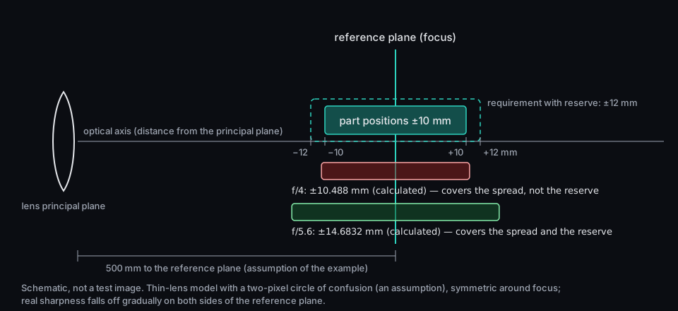
The result is one full interval, symmetric around nominal focus under a thin-lens approximation, so the half-range you compare with a part-position spread interprets that model rather than measuring a lens. Sharpness falls off continuously: a part a millimetre outside is not lost, and one just inside is not guaranteed.
Choosing the f-number between light and diffraction
The aperture is the opening that sets the cone of light through the lens, and the f-number is the focal length divided by the diameter of the entrance pupil (vendor documentation), so a larger f-number means a smaller opening and a wider interval. Take the minimum f-number whose interval covers the spread of part positions and the reserve you accept, then confirm that setting on the task.
Closing down costs light first: at f/5.6 the lens receives four times less than at f/2.8 in Edmund Optics' comparison, and that has to come back as exposure, illumination or pulse energy. Under continuous light the exposure may be lengthened as far as the motion-blur budget you calculated and tested allows. Under a pulse that dominates the image it may be longer still, provided the pulse duration meets that budget, the pulse falls wholly inside the window in which the rows you need are exposing, and ambient light leaves no trail. Motion therefore narrows the exposure you may use rather than forbidding a longer one, as the exposure and strobe article works through.
Diffraction is the second cost. Light spreads at the edge of an aperture, so the smallest spot a lens can form, the Airy disk, is roughly 2.44 times the wavelength times the f-number. Edmund Optics' 520 nm table gives 3.55, 7.11 and 13.96 µm at f/2.8, f/5.6 and f/11 (published reference table), about 1.03, 2.06 and 4.05 pixels against this camera's 3.45 µm pitch (calculated). The spot grows at every step, yet the picture need not follow it down, since stopping down also reduces aberrations and the image may improve before diffraction takes over, which is why the aperture is settled on a target of your own (Edmund Optics).
What "sharp enough" means for a code and for a measurement
For code reading the criterion belongs to the decoder, which has to reach its required read result on representative symbols, at the real light, across the depth range. A circle-of-confusion number is not a symbol-quality grade, which has its own method in ISO/IEC 15415:2024 for 2D symbols (normative), and reader vendors state image requirements per product rather than a universal depth boundary (vendor documentation). This branch answers in whole numbers: count reads and no-reads at each depth position.
For measurement the criterion is the error budget, so calibrated error and repeatability stay inside the share of the tolerance allocated to vision at every position the part takes. Cognex lists edge quality, the calibration target, the lens, mounting, image quality and tool accuracy as contributors and requires the complete system to be tested (vendor documentation). This result degrades gradually, so plot the error against depth, allowing for a part nearer the lens imaging larger; the pixels a feature needs are in the sampling and accuracy article.
Testing the extremes, and what to change when they fail
Focus at the reference plane, acquire the same representative target at the nearest and farthest position the part may take, and run the real decode or calibrated measurement on those frames, recording aperture, illumination and exposure with them. When an extreme fails, three levers remain.
- Verify where the focus actually sits by stepping the target through the allowed positions and seeing where the task performs best, because an interval centred on the part's near face wastes half of itself in front of the part.
- Lower the magnification, since the interval grows steeply as it falls: a wider field buys depth faster than the aperture does and costs pixels on the part, as choosing a lens when the working distance is fixed works through.
- Reduce the spread itself with a stop, a guide or a backing plate that holds the part against a known plane (practice).
Worked example: a 20 mm spread at a fixed 500 mm
The camera is the MV-CA050-12UM, 2448 × 2048 pixels on a 3.45 µm pitch (datasheet), which multiply out to an active area of 8.4456 × 7.0656 mm (calculated). The example assumes a 25 mm thin-lens geometry at 500 mm from the lens principal plane, a field of 160.4664 × 134.2464 mm, a magnification of 0.052632 (calculated), parts within ±10 mm of the reference plane and 2 mm of reserve on each side, so the interval has to reach ±12 mm.
| Aperture | Interval, calculated | Half-range, calculated | Airy at 520 nm, published table | In sensor pixels, calculated |
|---|---|---|---|---|
| f/2.8 | 14.6832 mm | ±7.3416 mm | 3.55 µm | 1.03 px |
| f/5.6 | 29.3664 mm | ±14.6832 mm | 7.11 µm | 2.06 px |
| f/11 | 57.684 mm | ±28.842 mm | 13.96 µm | 4.05 px |
f/2.8 fails on arithmetic, since ±7.3416 mm does not reach the ±10 mm the parts occupy. Run the intermediate stop first: at f/4 the same geometry returns 20.976 mm, or ±10.488 mm (calculated), covering the bare spread but falling 1.512 mm short of the reserve on each side. f/5.6 reaches ±14.6832 mm, 2.6832 mm beyond the ±12 mm requirement, with a diffraction spot about two sensor pixels across; f/11 covers nearly three times the spread for a four-pixel spot and less light again.
So f/5.6 is a candidate rather than a proved minimum: the f-numbers between and beyond these four were not all run, and lens MTF, illumination, exposure and task performance sit outside the arithmetic.
Calculate for your case
The prepared link opens the calculator with the camera, both field axes and the working distance of this example, so only your geometry is typed over them. Three values in that address answer other questions: a feature size of 0.1 mm, a five-pixel target and a speed of 0 mm/s. The aperture travels in neither the link nor the page, so all three examples share one address and none of them reproduces an interval there.
The aperture comparison goes through the optics route of the tools API, which does accept an fNumber parameter. The same geometry at f/4 and at f/5.6 returns the two figures compared above: read values.depthOfFieldMm, 20.976 and 29.3664 mm here (calculated). Replace those five parameters with your own case, and record the f-number next to the result.
Lens candidates for the aperture comparison
Four 25 mm C-mount lenses carry marked aperture ranges containing every aperture in the table: MVL-HF2528M-6MPE and MVL-MF2528M-10MPE at F2.8 to F16 with Ø9 mm and Φ11.2 mm image circles, MVL-KF2528M-12MP at F2.8 to F16 with Ø17.6 mm, and SA2520M-10MP at F2 to F22 with Ø23 mm (datasheet). A marking proves only that the iris can be set there. This camera's active area has a diagonal of 11.0114 mm (calculated from its resolution and pitch), which the Ø9 mm circle does not reach, the Φ11.2 mm circle exceeds by 0.1886 mm (calculated), and the two larger circles cover with margin. Send us the part number and we check the focusing range, the mount and the rest of that datasheet.
Common mistakes
- Treating the interval as proof shows up on the first production run, when near and far parts fail while the arithmetic approves them; that boundary comes from the two-pixel circle we chose, so take acceptance from a depth sweep with the real task.
- Reading "the smallest aperture" as "the minimum f-number" sends the iris to the far end of its range, where the station runs short of light for depth the task never asked for; name the f-number you mean, with the range and reserve it was chosen for.
- Reaching for f/11 because it returns the widest interval shows up as a frame that needs more gain while feature edges lose contrast instead of gaining it; its 520 nm diffraction spot is about four sensor pixels across (calculated), so compare settings on a real target.
When this rule breaks
The model is a thin lens and does not know the lens: the same number comes back for every 25 mm lens you might mount, in front of and behind focus alike. It also refuses a magnification below 0.001 instead of returning an unbounded interval.
The acceptance criterion is ours as well, and changing it changes only this arithmetic: a stricter task gets a narrower calculated interval and a looser one a wider one, while the range a decoder or a gauge actually holds is set by contrast, illumination, code quality, aberrations, motion and calibration, and has to be measured. Geometric focus is not contrast either, since MTF, the contrast a lens transfers at a given spatial frequency, can leave a lens the model calls sharp short of what the feature needs (Edmund Optics). Light level, pulse energy, exposure, gain and lens transmission also sit outside the calculation, so a marked aperture is not automatically usable at the exposure your line allows.
Next step
Send us the camera or the active sensor size, the field to cover, the working distance, the spread of part positions along the axis, the reserve you want held back, and the criterion you work to. We recalculate the interval across a range of apertures, name the lens candidates carrying those markings, and say what to acquire at the extremes.
Sources
- MVisionPro engineering calculator (public calculation core `public-calc-core-v1`) and Hikrobot catalog records (datasheet fields); calculations and catalog routes were verified on 2026-09-21
- Depth of field is the object-side range and depth of focus the image-side tolerance; stopping down increases depth of field while reducing irradiance, and f/5.6 receives four times less light than f/2.8 in the stated comparison: Edmund Optics, https://www.edmundoptics.com/knowledge-center/application-notes/imaging/depth-of-field-and-depth-of-focus/ (checked 2026-09-21)
- The f-number is the focal length divided by the entrance-pupil diameter, so a larger f-number corresponds to a smaller aperture: Basler, https://www.baslerweb.com/en/learning/lens-selection/ (checked 2026-09-21)
- Airy-disk diameter is approximately 2.44 × wavelength × f-number; the 520 nm table gives 3.55 µm at f/2.8, 7.11 µm at f/5.6 and 13.96 µm at f/11: Edmund Optics, https://www.edmundoptics.com/knowledge-center/application-notes/imaging/limitations-on-resolution-and-contrast-the-airy-disk/ (checked 2026-09-21)
- Aperture choice is judged on a representative test target, because stopping down trades decreasing aberrations against increasing diffraction: Edmund Optics, https://www.edmundoptics.com/knowledge-center/application-notes/testing-and-detection/choosing-the-correct-test-target/ (checked 2026-09-21)
- MTF describes contrast transfer versus spatial frequency, so a lens in geometric focus can still fail to deliver feature contrast: Edmund Optics, https://www.edmundoptics.com/knowledge-center/application-notes/imaging/mtf-curves-and-lens-performance/ (checked 2026-09-21)
- A short controlled pulse freezes motion and must fall inside the window in which the rows being used are exposing: Gardasoft, https://www.gardasoft.com/boost-capability-with-pulsed-lighting/ and Basler Flash Window, https://docs.baslerweb.com/line-source#flash-window (checked 2026-09-21)
- Calibration accuracy depends on edge quality, calibration target, lens, mounting, image quality and tool accuracy, and complete-system accuracy must be tested: Cognex, https://docs.cognex.com/is_613/web/EN/ise/Content/How_To/Calibration/CalibrationAccuracy.htm (checked 2026-09-21)
- ISO/IEC 15415:2024 specifies methods to measure and grade attributes of 2D symbols: https://www.iso.org/standard/76876.html (checked 2026-09-21)
- Product-specific image requirements for a code-reading tool, in place of a universal depth boundary: Cognex ReadIDMax, https://support.cognex.com/docs/is_651/web/EN/ise/Content/Reference/ReadIDMax.htm (checked 2026-09-21)
Related
How this material was prepared
Prepared with MVisionPro AI agents from stated sources and the calculation core; MVisionPro retains editorial responsibility. A physical test or human engineering review is claimed only when explicitly stated. Read the editorial method.
Editorial status: verified. Content updated 2026-09-21.